
What is Link Load Balancing.
The Citrix ADC appliance uses LLB to monitor and regulate traffic, ensuring that packets are sent over the best possible network. Outbound traffic is balanced via link load balancing (LLB) over numerous Internet connections offered by different service providers.
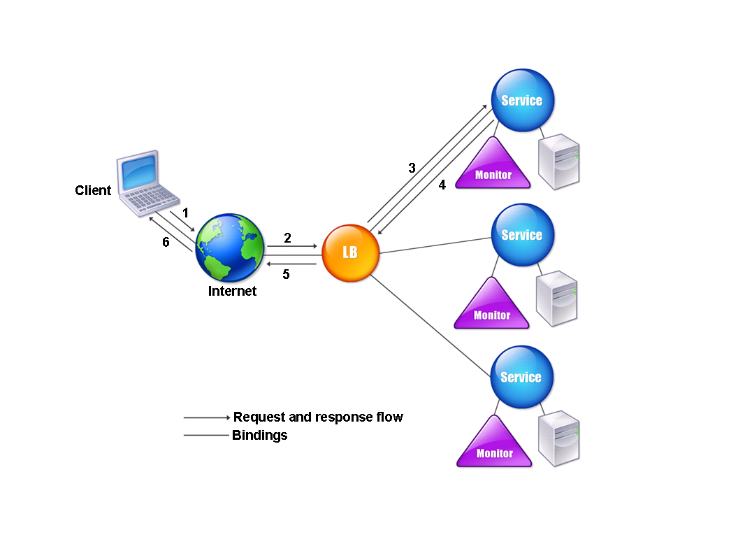
The Citrix ADC appliance and the router are connected through a link. Configuring a basic setup with default parameters while configuring link load balancing is the most common scenario. Services, virtual servers, monitors, routes, an LLB method, and persistence are all part of a basic configuration (optional). You can customize a basic setup for your environment once it is operating.
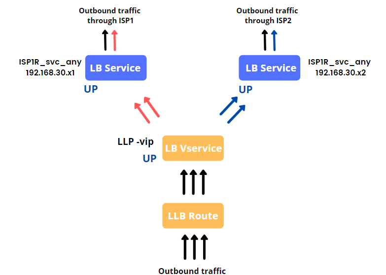
There are two Link Load Balance services available with 192.168.30.x1 and 192.168.30.x2, and traffic data travels through the efficient internet service provider, as shown in the example below,
For connections to be sustained on a specific link, you can optionally configure persistence. Source IP address-based persistence, destination IP address-based persistence, and source IP and destination IP address-based persistence are all options. The default monitor is PING, although setting up a transparent monitor is advised. Configure reverse NAT (RNAT) and backup links to personalize your system.
Below are the different components for configuring Link Load Balancing,
- Services : – Services are applications that run on a server. While services are typically combined with virtual servers, a service can still manage application-specific traffic in the absence of a virtual server. In case of load balancing, where service represents a server, a service in LLB represents a router or the next hop.
- Virtual Server: – Virtual servers configured on the appliance provide connection points that clients use to access the applications behind the appliance in a typical installation. Virtual servers are used to map LLB services, and those services are then represented for each individual link (router or next hop).
- Load Balancing Methods: – The methodical and efficient distribution of network or application traffic across multiple servers in a server farm is referred to as load balancing. Each load balancer sits between client devices and backend servers, receiving and distributing incoming requests to any server that can fulfill them.
The following load balancing methods are supported,
|
LEASTCONNECTION |
Which service has the fewest client connections right now. |
|
ROUNDROBIN |
Which service is at the top of a list of services. After that service is selected for a connection, it moves to the bottom of the list. |
|
LEASTRESPONSETIME |
Which load balanced server has the fastest response time right now |
|
URLHASH |
A hash of the destination URL. |
|
DOMAINHASH |
A hash of the destination domain. |
|
DESTINATIONIPHASH |
A hash of the destination IP address. |
|
SOURCEIPHASH |
A hash of the source IP address. |
|
SRCIPDESTIPHASH |
A hash of the source and destination IP addresses. |
|
CALLIDHASH |
A hash of the call ID in the SIP header. |
|
SRCIPSRCPORTHASH |
A hash of the client’s IP address and port. |
|
LEASTBANDWIDTH |
Which service currently has the fewest bandwidth constraints. |
|
LEASTPACKETS |
Which service currently is receiving the fewest packets. |
|
CUSTOMLOAD |
Data from a load monitor. |
|
TOKEN |
The configured token. |
|
LRTM |
Fewest active connections and the lowest average response time. |
4. Persistence Method
If you want to keep the states of connections on the servers represented by that virtual server, you must configure persistence on that virtual server . The appliance then selects a server using the defined load balancing mechanism, however all subsequent requests from the same client are forwarded to the same server.
Once the server has been selected, the load balancing algorithms are overridden if persistence is enabled. If the configured persistence applies to a down service, the appliance selects a new service using load balancing methods, and the new service becomes persistent for subsequent client requests. If a service is marked as Out Of Service, it will continue to serve existing requests but will not accept new ones or connections. Existing connections are closed after the shutdown period expires. The forms of persistence that you can configure are listed in the table below.
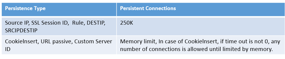
Table 1. Limitations on Number of Simultaneous Persistent Connections
The load balancing methods are utilized for server selection if the configured persistence cannot be maintained due to a lack of resources on an appliance. Depending on the persistence type, persistence is kept for a specified amount of time. Some types of persistence are only available on certain virtual servers. The relationship is depicted in the table below.
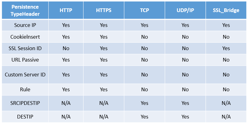
Table 2. Persistence Types Available for Each Type of Virtual Server
Persistence can also be specified for a set of virtual servers. Client requests are directed to the same specified server when you enable persistence on the group, regardless of which virtual server in the group gets the client request. When the persistence timer expires, any virtual server in the group can be used to handle incoming client requests.
- Monitor:- (Ping , Transparent)
The link load balancing monitor can be used to manage the various attributes: overall traffic view, certificate management, scalability, web application firewall insight, and latency awareness.
Ping and transparent are two approaches for monitoring LLB.
- Ping :-
The default PING monitor simply monitors the connectivity between the Citrix ADC appliance and the upstream device.
2. Transparent:-
You construct a transparent monitor to look on upstream equipment like routers. The transparent monitor can then be bound to services. The transparent monitor keeps track of all devices in the path between the appliance and the device with the destination IP address. The appliance includes the router while conducting load balancing and transmits the packet to the router if a transparent monitor is not configured and the router’s status is UP but one of the next hop devices from that router is down. However, because one of the next hop devices is down, the packet is not transmitted to the destination. By connecting a transparent monitor, you can.
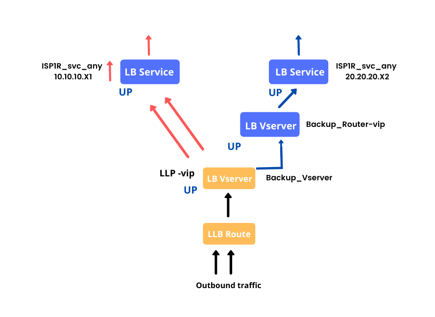
Backup route
You can set up a backup route to prevent service disruptions if the primary route goes down. When the primary route fails, the Citrix ADC appliance immediately switches to the backup route. To begin, configure an LLB virtual server and bind a service as explained in Configuring an LLB Virtual Server and Binding a Service.
Create a secondary virtual server that is comparable to a primary virtual server and then designate it as a backup virtual server to configure a backup route (route). Router-vip is the primary virtual server, and Backup Router-vip is the secondary virtual server designated as the backup virtual server, as shown in the diagram.
Figure 1. Backup Route Setup
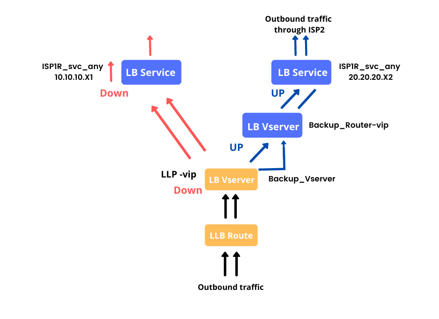
Note: Replace the IPv4 service with an IPv6 service if your ISP has given one.
Figure 2. Back up Routing in Operation
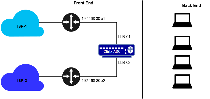
To demonstrate the link load balancing feature, we have two internet service providers, ISP-1 and ISP-2, connected via router as shown below, and a Citrix ADC attempting to balance the link load between both internet service providers. This entire setup supports the link requirement for systems, which are depicted as backend systems.
Lab Design:
Lab Instance:
|
Instance Name |
IP |
Description |
|
ADC |
192.168.30.x |
Citrix ADC Box |
|
LLB-01 |
192.168.30.x1 |
Service representing to internet connection |
|
LLB-02 |
192.168.30.x2 |
Service representing to internet connection |
|
LLB-VSRV-01 |
No-Address |
Virtual Server for LLB |
|
LLB-VSRV-Backup |
No Address |
Virtual Server for Backup Link |
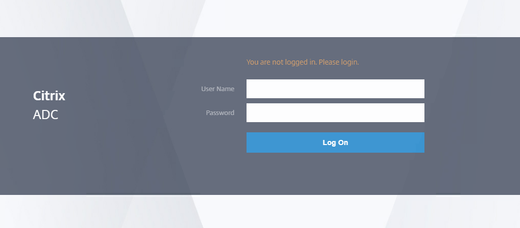
Step-1: Connect to Primary ADC:
Open Google Chrome and connect to Primary ADC using NSIP https://192.168.30.x.
Log on using the credentials:
Step-2: Create the LLB Router Services:
Browse to Traffic Management > Load Balancing > Services >Click Add
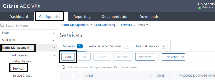
Enter the following Service information for the llb01 router:
- Service Name: LLB-01
- Verify that the radio button is set to: New Server
- IP Address: 192.168.30.x1
- Protocol: ANY
- Port: *
- Click OK.
- Click Done on the following window.
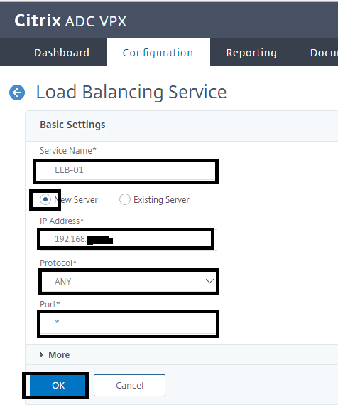
Enter the following Service information for the llb02 router:
- Service Name: llb02
- Verify that the radio button is set to: New Server
- IP Address: 192.168.30.x2
- Protocol: ANY
- Port: *
- Click OK.
- Click Done on the following window.
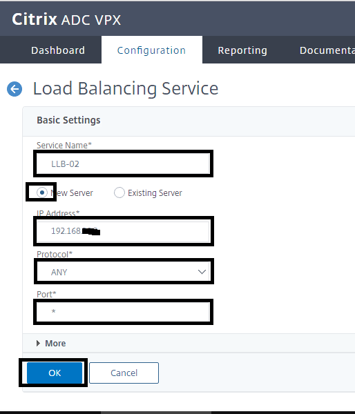
Verify that the services are UP or not
Step-3: Create a Link Load Balancing virtual server:
- Browse to Traffic Management > Load Balancing > Virtual Servers.
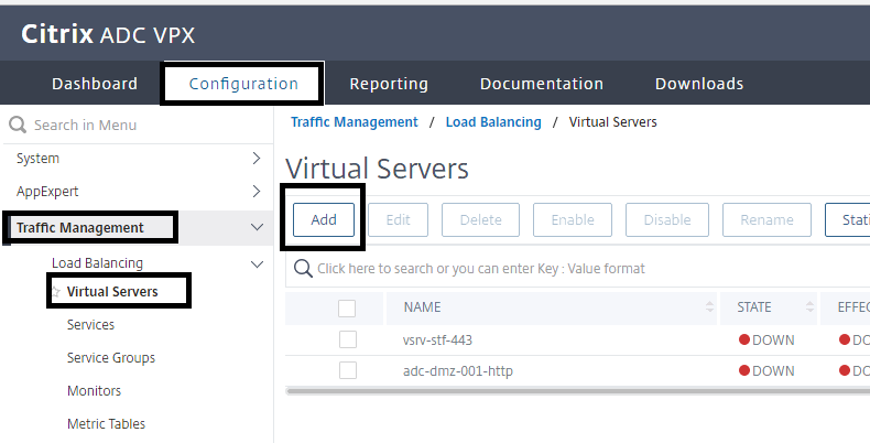
- Click Add.
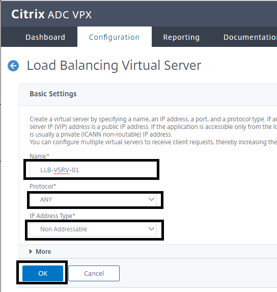
Enter the Load Balancing Virtual Server information:
- Name: LLB-VSRV-01
- Protocol: ANY
- IP Address Type: Non-Addressable
- Click OK
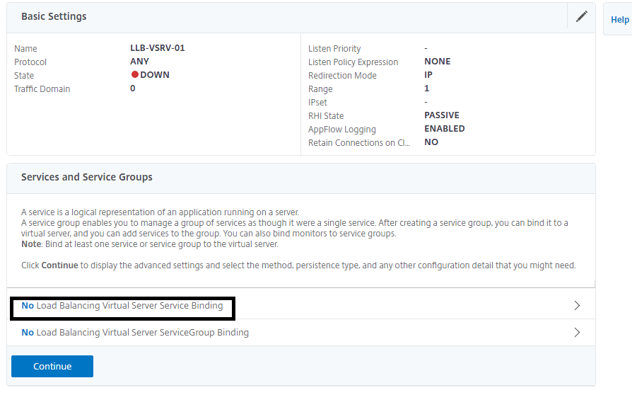
Step-4: Bind the Services to the Load Balancing Virtual Server:
- Click No Load Balancing Virtual Server Service Binding.
- Click on Click to Select
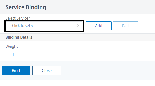 .
.
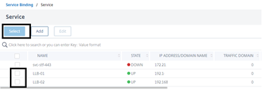
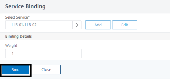
- Select the check boxes for Services LLB-01 and LLB-02, and then click Select.
- Click Bind.
- Click Continue
Step-5: Define the load balancing Method to Round Robin:
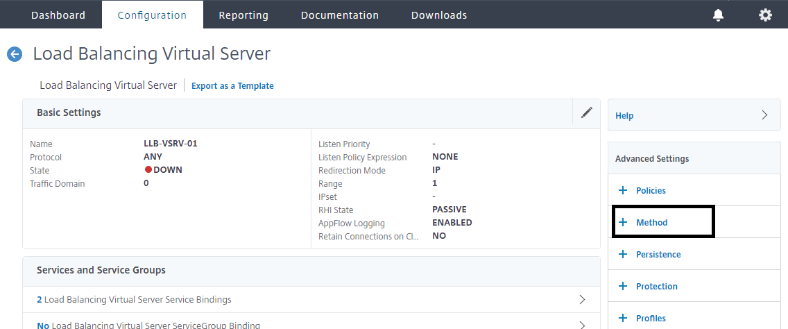
- Click Method under Advanced Settings.
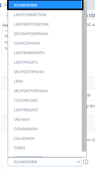 Under Method, make sure that ROUNDROBIN is selected for the Load Balancing Method box,
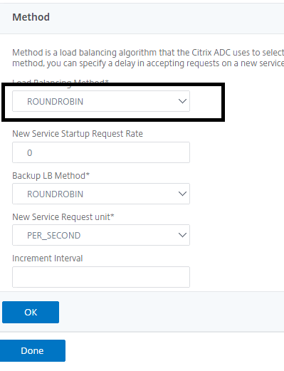
- Click OK.
Step-6: Select a Load Balancing Persistence Method:
- Under Advanced Settings, click Persistence.
- Under Persistence, make sure that the SOURCEIP is selected for the Persistence box, and then click OK.
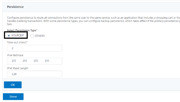
- Click Done.
Step-7: Verify that the Load balancing Virtual Server LLB-VSRV-01 is UP
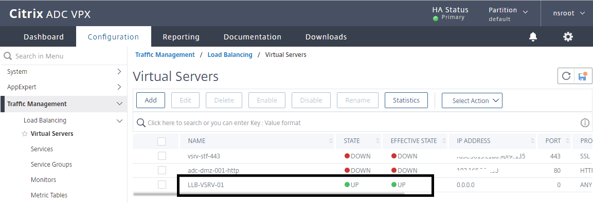
- Save the ADC configuration
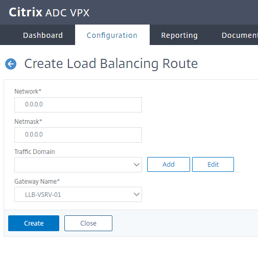
Step-8: Configure the LLB route:
- Browse to System > Network > Routes, and then select LLB to configure an IPv4 route.
- Click Add.
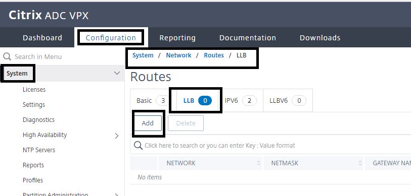
Enter the route information:
- Network: 0.0.0.0
- Netmask: 0.0.0.0
- Leave the Traffic Domain Blank.
- Gateway Name: LLB-VSRV-01.
Click Create
Step-9: Creating and Binding a Transparent Monitor
Create a transparent monitor for LLB-MON-01:
- Browse to Traffic Management > Load Balancing > Monitors.
- In the Monitors pane, click Add.
In the Create Monitor dialog box, configure the following parameters:
- Name: LLB-MON-01
- Type: Click on Click on Select
- select PING
- Under Advanced Parameters, Destination IP: 192.168.30.x1
- Select the checkbox for Transparent.
Click Create.
Create a transparent monitor for LLB-MON-02:
- In the Monitors pane, click Add.
In the Create Monitor dialog box, configure the following parameters:
- Name: LLB-MON-02
- Type: Click on Click to select and select PING
- Under Advanced Parameters, Destination IP: 192.168.30.x2
Step-10: Bind the monitor to the service:
Bind the LLB-MON-01 monitor to the LLB-01 service:
- Browse to Traffic Management > Load Balancing > Services.
- Select LLB-01 and click Edit.
- Under Monitors, click 1 Service to Load Balancing Monitor Binding.
- Click Add Binding.
- Click Click to Select.
- Find you monitor in list.
- Select the checkbox for LLB-MON-01 monitor, and then click Select.
- Click Bind
Bind the LLB-MON-02 monitor to the LLB-02 service:
- Browse to Traffic Management > Load Balancing > Services.
- Select LLB-02 and click Edit
- Under Monitors click 1 Service to Load Balancing Monitor Binding.
- Click Add Binding.
- Click on Click to Select.
- Select the checkbox for LLB-MON-02 monitor, and then click Select.
- Click Bind.
- Click Close.
- Click Done
- Configure a Backup Route:
In this scenario, I’m going to set up LLB-02 as a backup link. So, first and foremost, I will unbind LLB-02 from the link load balancing virtual server and bind it to a new virtual server that will function as a backup link.
Step-1: Unbind the LLB-02 Service and use it for the Backup Route:
- Browse to Traffic Management > Load Balancing > Virtual Servers.
- Select LLB-VSRV-01 and click Edit.
- Select 2 Load Balancing Virtual Server Service Bindings.
- Select the LLB-02 service and click Unbind.
- Click Yes to Confirm.
- Click Close.
- Click Done
Step-2: Configure a backup Link Load balancing Virtual Server to add as a backup route:
- Browse to Traffic Management > Load Balancing > Virtual Servers.
- Click Add.
- Name: LLB-VSRV-Backup
- Protocol: ANY
- IP Address Type: Non-Addressable
- Click OK.
Step-3: Bind Service to the Virtual Server:
- Click No Load Balancing Virtual Server Service Binding.
- Click Click to select.
- Select the checkbox for LLB-02 and click Select.
- Click Bind.
Click Continue.
Step-4: Configure the backup route:
- On the Virtual Servers pane, select the checkbox for LLB-VSRV-01 and click edit.
- Click Protection on the right pane.
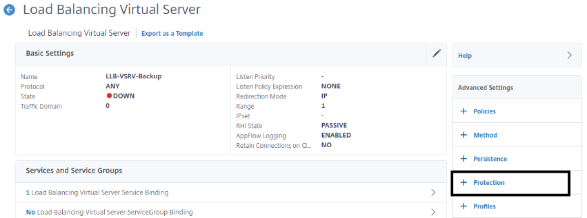
- Under Protection, make sure that the LLB-VSRV-Backup is selected for the Backup Virtual Server box.
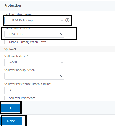
- Click OK.
- Click Done.


Mani, thank you for this detailed article. Brilliantly written!